
Lockley, Norris 'Bespoke of Settle'
Posted: Tuesday 02nd June 2020
Fillet-brazing, or bronze-welding as it is known in the UK, is a technique that, like many other skills needs practice to make good. There are however other considerations and preparations that should be made before the torch and rod are even approached to the frame’s joints. Preparation makes perfect! I was lucky in being taught to braze and bronze-weld by the chief instructor at the British Oxygen Company in London. Other than that his main claim to fame was that he developed the manufacture of the “black box” flight recorder containers by welding them up in osmium.
His party piece for his trainees was to tear in half the aluminium foil container from an apple or plum pie – just think how thin those things are – and weld it back together. For the neatest bronze-welding we were taught not to use the standard brazing flux such as SIF-BRONZE but to apply a special “antiporosity” one. No flux would be applied to the cleaned up joint but it would be applied during the welding process by dipping the end of the rod into the tin of flux. This type of flux helped to control the sideways spread of the bead, kept the outer margins very straight and true, and limited the amount of zinc that would be boiled out of the molten weld material in the event of the torch’s flame not being precisely set up, i.e. the oxygen/acetylene balance.
With reasonable care, and accurate settings of the gauges and the gas mix at the torch, very accurate and neat beads with evenly spaced ripples will result. To then convert the ripples into a smooth finish as Norman used to do it is necessary to take a small nozzle – I use a No. 1 – and to set up the flame very accurately with as small a gas-balanced flame as possible. This shows as quite a tiny flame with a miniscule blue inner cone. The flame is focussed on the weld joint to be made with the tip of the blue inner cone almost but not quite touching the bronze filler rod.
The process is not a fast one but once started it is and must be a continuous one if a smooth surface is to be the outcome. Once the parent weld metal has started to melt and a small molten pool is available at the tip of the flame, the flame is played and stroked from side to side and onwards over the bead. Because the pool, or “onion” of molten metal is so small, it is easily controllable. A steady hand, a good eye, and a reasonable amount of patience and practice will produce the required smooth and shiny bead. Remember always – you are in control of that torch with the molten metal at its tip – it’s a very rewarding feeling. Oh….! and I always find that I get the best results if I have a piece of peaceful non-intrusive music such as Beethoven’s Pastoral Symphony, Elgar ‘s Enigma Variations, or even the lyrical Songs of the Auvergne playing in the background. And don’t forget to wear your welder’s tan leather skull-cap either.
I understand from my recent research that many French frame builders, particularly the constructeurs, used to wear the traditional Breton beret as they welded up their frames. If you are a smoker, try lighting up a Gauloise or Gitane cigarette as these particular brands are known to produce very long ash residues sometimes up to three centimetres in length that cling to the end of the cigarette. The longer the ash, the smoother the finished bead.
Some dozen or so years ago I had the great pleasure, while sharing a very large pork pie with Norman and Jack at the CTC’s York Rally, of asking Norman how much time he spent in filing up the beads, whether he did the finishing as the frame-building process went from stage to stage, joint to joint, if he filed up each joint as soon as he had brazed it or whether he completed the whole frame and then set about filing it.
I asked as for some long years I had been building a lot of lugless frames, including some tandems, and I had developed the system of filing up each weld as I went along, e.g. the head tube to top tube joint, before this assembly was joined to the down tube or the seat tube. To my mind there was nothing more difficult, time-consuming, and awkward than trying to hold a completed frame, main triangle and stays intact in a vice and trying to perform accurate and fine finishing of the welded joints.
I suppose that in asking Norman the question I assumed that after so many decades of frame-building he must have perfected a technique that he could offer to slightly younger builders such as myself. I remember Norman cocking his head to one side a little, screwing his eyes up inscrutably as he pondered the depth of my questioning, or perhaps the sun was shining in his direction, and delivering in his Geordie accent the words of wisdom – “I don’t!”
He went on to explain that after welding a joint he would change the torch’s nozzle for the smallest in the box and just use it to “tickle over the ripples…smooth them out…like”. As Jack explained, in order to provide additional clarification – “We’re frame-builders, lad, not mechanical engineers!” I think that one of the last shots in the film made of the Taylor’s building techniques, shows Norman holding a tandem frame vertically. As he revolves it with one hand, with the frame’s rear drop-out acting as a pivot against the floor of the workshop, with a torch in the other hand he is gently wafting the tip of the tiny flame over a bead of bronze welding material.
To summarise the technique further Norman added, “And what doesn’t come off when we sand-blast the frame just stops on. The technique of gently flushing the ripples of a bead of welded bronze into a smooth surface is not a difficult one, as long as the flame is very small and you keep it moving over the bead, flicking it gently and carefully from side to side. The process is better than Valium for calming the nerves!”
Norris on the problem of filling the voids that occur in the internal joints created by frame tubes and badly pressed steel lugs. Frame builders become well aware of the shortcomings of many of the frame components that they have to use when constructing a frame; in particular the tolerances and accuracy of many pressed lugs leaves much to be desired. The void between the radiused internal angle of a lug is probably the biggest problem, or at least filling it with brazing material is. I was around in the early days of the 1950s when frame components were in short supply and the choice when building a frame was often either to adapt as best as possible old style and slack-angled cast lugs, or construct the frame without lugs.
Another option used by some was to use the bi-laminated technique. But with the easing of the supply of raw materials along came supplies of pressed lugs, notably Franco-Suisse, Prugnat (in very short supply) and Oscar Egg Super Champion. All these lugs suffered from the internal radius problems i.e. voids or empty pockets in the joint that did not exist in cast lugs. The way I was taught to overcome the problem was quite ingenious. It made more work but it was a technique that was easy to employ, in a sense, because we built the frames without the aid of jigs. We started the brazing process by brazing the top head-lug to the top-tube, and by brazing the bottom head lug to the down tube. Note that the head tube is not mentioned.
We would braze these joints by applying the filler rod from inside the lug and drawing it through the joint and along the tube. The void would then be over-filled. When cool the surplus braze material on the inside of the lug would be carefully filed to ensure that the void no longer existed and that the joint had a perfect mitred profile so that to all intents and purposes the inside of the lug was as accurate as a cast one. Later on we bought an expanding reamer that gave more precise profiles and diameters.
When we had filled these joints we carried out the same process by attaching the seat lug to the other end of the top tube, backfilling the joint with braze material and then filing away the surplus. Once the top-tube head-tube and down-tube were assembled and ready for brazing we would carry out the process with silver solder that melted about 230 degrees lower, thereby ensuring that the braze material in the voids would not be melted and the integrity of the joint not compromised. The same process was applied to the seat tube joint. As for the bottom bracket joints and chainstays, the brazing rod was applied from the inside of the shell and sucked up the tubes. Back-filling any radii in the bracket was quite easy.
In later years and following training with the British Oxygen Company I became much more proficient in controlling the movement of brazing spelter with the torch flame within a lugged joint and also outside on lugless frames. I abandoned my early void-filling technique and became very skilled at filling the voids by using an externally applied rod of thicker than normal diameter, say about 1/8″, and a smaller than normal nozzle, usually a No1. With the much smaller flame I could almost stroke and coax the slightly pastier filler rod into the voids, by controlling the heat and the rate of flow of the braze material at the same time. As my tutor at the BOC always said, “always use the smallest nozzle possible. It may take a little longer, but a craftsman with a lighted torch in his hand should never be in a hurry”.
Queries about the suitability of this particular tubing (Reynolds 531SL) set crop up on a regular basis, either regarding its use for frames for heavier riders or about some of the faults it was supposed to, and in certain senses, did actually have. It should be remembered that this tubing had been about in the 50s, when it was just one of the various gauges of the standard 531 DB that were available to help build lighter frames. I don’t recall there being any restriction on or suggestion of a recommended maximum weight in those days. Indeed I remember top-builders such a Pat Skeates, Clive Stuart, Hilton Wrigley using the lighter tubes for frames as large as 24″ – some of my clubmates rode these sizes. but only for fast road bikes, and not touring or track machines.
The metallurgy of the tube, i.e. the alloying elements are the same as those for the standard 531 DB…and no special care needed to be exercised, unlike with 753 that emerged later, which had a different metallurgy. I remember talking to the Reynolds representative when the Series 531SL was launched in the mid-70s and recall that he urged the use of silver-solders rather than silicon brazing alloys, in order to limit the heat input required. However, this recommendation was due to the use of finer gauged tubes, not to alloying elements. It should be remembered also, that when the lighter gauge 531 DBs were in use in the 50s, many builders were using different types of heat sources and gas mixtures.
The age of the ubiquitous oxy-acetylene torch had not really dawned. In those days I was using coal (town gas) and compressed air. This gave a much larger, softer and less hot flame. The large flame actually enveloped the whole of a lugged joint with what we called a brush flame. It was easy, but took longer, to heat the whole joint area to the same temperature without any fear whatsoever of over-heating or burning the tubing..resulting in the brazing alloy running very freely throughout the joint. Reynolds 531SL got itself a bad name when frames started cracking on the chainstays.
This was not due to any problem with the steel per se, but to the manner in which Reynolds had put the dented area, adjacent to the point where the chainring would spin. Additionally, the gauge of the seat stays and, I believe of the chainstays, was reduced. This lack of stiffness gave rise to the rear of the frame flexing under load. When the set re-emerged as 531 Pro, with slight reworking of seatstay sections, and indentations of the chainstays, the flexing had not been removed sufficiently … which led in turn to 653, in which the rear end stays were made up of 753 components. The problem was then resolved. However, the Peugeot Pro team used 531SL frames with great success in the late 70s. Perhaps flex and stiffness are all relative terms and open to individual interpretation.
Building a frame with the Nervex lugs by Norris Lockley (including some history of the origins)
I am/was a framebuilder and I still do have several full sets of these lugs in stock so I am always interested in seeing what other builders think of them and how they have adapted them. This article is sent to add a little bit of the historical background to the company and the development of the Series Mk1 and II of the Nervex Pro set.
In the late 40’s and early 50’s most British framebuilders relied upon cast lugs with which to build their frames. These could be from English manufacturers such as Vaughan, Davis, Brampton, Chater-Lea etc or from European manufacturers such as Aerts, or EKLA. As the European economy picked up after WWII supplies of more modern lugs started to be imported, most of which were made from precision pressings of mild steel plate by a process called “emboutissage”. Amongst the very first of these, and very popular with builders, were the excellent Oscar Egg “Super Champion” models. By about 1953 builders such as JRJ in Leeds (later to become Bob Jackson cycles) were also offering the Nervex range of lugs as an option to these other brands. JRJ also offered, as did several other builders that I know of, the Franco-Suisse range.
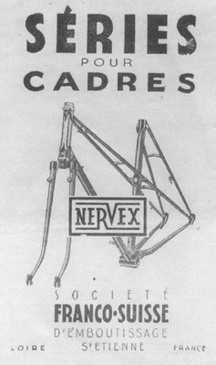
I started helping a frame-builder in about 1953/54 and up until that time I had not heard of Nervex lugs, but was aware of Franco-Suisse. My recent research, as demonstrated by the Franco-Suisse advert from February 1950 (see image left), indicates that in fact the two brands were one and the same, Franco-Suisse, a firm in St Etienne, France, being the manufacturer, and Nervex being the brand of lugs that it manufactured.
It would appear from further research that Ste Franco-Suisse either sold out to, or changed its name to, Francolam, the name that appears on the box of lugs in the main Nervex article, and on the cover of the much-quoted and referred-to Nervex lug and parts catalogue for 1957.
Although the Nervex Pro MkII lug set, with its fish-tail design, has proven popular for the best part of fifty years, the fork crown, with its two short prongs, has not caught cyclists’ imaginations to the same extent. It is only in the last ten years that I have actually bought some of these crowns as NOS and so I have no idea how much they cost originally. My own theory about their lack of popularity is that the crown was an early pressed model made by Franco-Suisse, to match up with the head lugs of the Pro MkI lugset, that also had two short spikey prongs. Whether or not what is now referred to as the Nervex Pro Mk I lugset was actually at the time known as the Franco-Suisse I can only conjecture. Perhaps the Nervex Pro Mk II with the fish-tail feature was the first lug produced by Francolam and marketed under the Nervex name. I doubt that we will ever know the full story.
The Pro crowns are in a sense a triumph of “emboutissage” but the method of manufacture did create two gaping cavernous holes inside the crown that it would have been impossible to fill with brazing alloy. Even a well-brazed crown would only have line contact around the perimeters of the holes and along the fancy cut-out and tangs resulting in a somewhat weak construction. On the other hand, around the early 50s, companies such as EKLA and Wagner had started producing very strong accurately cast steel models that gave full contact areas for brazing between the column, fork blades and the crown itself. Any self-respecting frame-builder would prefer to use either cast or forged crowns, they resulted in much stronger and better performing fork units that were less likely to bend in use or from which the blends could not work loose due to the lack of brazed area and contact.
From the frame-building point of view, builders found the Nervex Pro Mk II set to be very good in that it offered a hand-cut look without having to expend the time and effort of drilling and filing, and yet it lent itself to being altered and embellished in several ways. The other advantage, one that should not be overlooked, was that the sets were offered in a variety of angles that either suited frames straight out-of-the-box, or could be adapted with little effort. The practicality of using the lug was, however, quite different because, fresh out of the box, all the lugs needed quite a lot of attention to clean up the stamped-out curved profiles that often appeared to have been nibbled rather than cleanly cut. This criticism applied particularly to the three pipes, i.e. those tubular parts that held the top and down tubes.
Internally the lugs were very accurate in their angles and diameters, with very few and only small voids in the junctions between the upper and lower mitres. The side inner profiles of the mitres were reamed very precisely, thereby eliminating any sloppiness of fit. The closeness of internal fit meant more accurate frames and also the need for less brass to fill voids and less heat to apply it and to make it run into those voids, i.e. backfilling of the joints.
However this accuracy came at a price, that being that the pressure applied on the external surfaces by the machines forming the lugs, often left deepish grooves along the mitres. Some builders would spend hours filing the whole of the pipes to reduce the thickness of the metal in attempts to obtain a smoother overall finish, while others would run lines of bronze welding into the grooves and then smooth this into the pipes.
The real labour of using Nervex Pro lugs was the time it took to thin down and taper the pipes either in preparation before brazing, or afterwards when cleaning up and finish-filing. Those litte squiggles and swirls, particularly the fish-tails central to the head lugs, took a lot of skill and care, if a neat and harmoious effect was to be obtained.
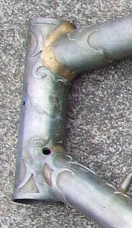
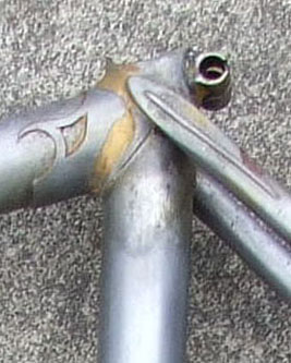
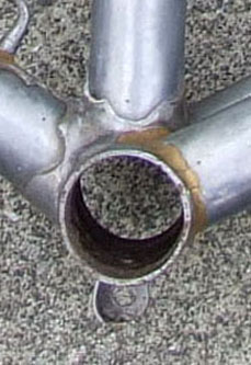
The 1952 Ephgrave No. 1 frame shown below obviously had signs of deviation to the brazing normally expected with a lugged frame. It was thought that maybe it was a bi-laminated version of the No. 1. Norris however came up with a different theory based on his years as a framebuilder and this is produced below the images.
As I have mentioned before I am somewhat fascinated by the bilaminated method of building frames and have used the technique on quite a lot of occasions for a variety of differing reasons; if nothing else the bilaminated technique offers the builder a terrific amount of freedom, particularly if he is intent on building custom i.e. made-to-measure frames as opposed to standard models.There has been a considerable upsurge in the amount of interest shown by collectors in frames built with this method, but, in my opinion there have been many false assumptions and interpretations. Into this category falls, I am certain, the Ephgrave No1 Super ‘Bilaminated frame No 263LE that you have just featured in your pages. This frame is an example of the earlier model that did not feature long spearpoints; all the frames (or rather all the No1 frames that I have seen with the early pattern lugs) have been built with EKLA malleable cast lugs. These lugs with their very thick walls and ‘cheeks’ are cast in a precise angle and the holes for the tubes are machined /reamed at that angle. Although the lugs are named as ‘malleable’ they cannot be reworked, bent, blacksmithed etc etc to take on any other angle without great difficulty and also without the danger that the holes would distort, rendering quite expensive lugs worthless.. destined only for the scrap box.
As your article states, supplies of frame parts were often difficult to obtain in post-WWII Britain, and under these circumstances no frame-builder would take that risk. The red No1 Super frame with the extra windows and the spearpoint embellishment of the headlugs is a later frame whose lugs are not malleable cast, but in fact pressed steel plate. Unlike the malleable ones these lugs can be reworked into different angles quite readily. Having studied the photos of the MkI No. I Super frame and enlarged them, I am convinced that the frame has not been built by the bilaminated system. Instead I think that Ephgrave had decided that this particular frame needed angles that differed from those offered by a standard set of EKLA lugs. Because it would have not been feasible to adapt or rework the cast EKLA lugs he decided to alter then by cutting, by sawing off , the pipes from the lugs ie separating the top-tube pipe from the head-tube one. These pipes would then be brazed to the tubes, the ensembles would be mitred to the required angles and then the lugs bronze-welded back together
One way to alter the angle of a pressed steel lug is to make saw cuts on both upper and lower faces of the lugs and then to insert tubes into the pipes and gently bend and persuade the relatively thin steel sheet to adopt the required angle. This would not be possible with a cast lug without the danger of either the casting breaking or the holes distorting If you examine a bronze-welded joints on most bilaminated frames, when they are in the raw steel state, you would note that the beads of sif-bronze welding material are more substantial than those on the EKLA lugs. You don’t have to examine the photos of the three lugs too closely to notice that there is more bronze weld bead on the upper head tube and the seat tube lugs than there is on the lower head-tube lug. You will also notice that the top-tube pipes on both the upper head-tube lug and the seat-cluster one are longer and more substantial than the down-tube pipe on the lower head-tube – this latter lug having only a very small amount of bronze bead..and certainly not a full continuous bead that encircles the whole joint.
This leads me to conclude that Ephgrave cut both the upper head and the seat lug in half in order to reprofile the angles but was able to alter the less robust down-tube lug by just putting a saw nick in the upper angle and very carefully ‘pulling’ the angle The fact that the chainstay-to-bottom brackjet pipes are missing leads me to think that the change in angles also dictated a slight change in the bottom bracket height and chainstay angle. Because the chainstay pipes were so short and incapable of being reworked, Ephgrave decided to dispense with them altogether. I think that this theory holds water and is justified by the fact that the frame uses an Osgear fitted to a bracket brazed underneath the bracket shell as opposed to having the tension arm clamped around the lower end of the down-tube.
The difference in location of the arm would render the pulley lower,and nearer to the ground. I think that Ephgrave actually raised the bracket height to give extra ground clearance to the pulley. All of which is my personal interpretation of how Ephgrave constructed this particular frame. If nothing else my thesis should provoke some reflection on the part of collectors of Ephgrave frames. I reckon that if you could assemble a random sample of about twenty early No1 Super Ephgrave frames and sand-blast the paint off all of them..you would find more….falsely identified bilaminated frames.
Posted: Tuesday 02nd June 2020
This article appears in the following categories.
Upcoming Events
Whether you are looking for a gentle social meet up, or a 100-mile ride browse the community’s upcoming events and plan your next weekend outing.